

Universal Pumping | High Pressure Pumps
High Pressure Pumps for Difficult to Pump Slurry, Sludge, and Food Waste.
Why choose diaphragm pumps for industrial applications? The answer begins with control, containment, and practical resilience. In chemical, food-processing, wastewater, and mining facilities, fluids rarely behave perfectly. They may contain solids, change viscosity, or resist ordinary mechanical seals.
Diaphragm pumps isolate the pumped liquid from moving drive components. This design can reduce leakage risks and support reliable handling of corrosive or abrasive media. They can also run dry for limited periods, tolerate fluctuating flow, and deliver gentle transfer for sensitive products. These advantages matter beside a stainless-steel tank, where a small seal failure can quickly become a costly cleanup.
The energy question deserves attention. The U.S. Department of Energy’s Improving Pumping System Performance sourcebook reports that pumping systems may consume nearly 20% of industrial electricity. In some facilities, pumping can represent 25% to 50% of total electricity use. Therefore, diaphragm pumps should not be selected by purchase price alone. Air-operated models may provide excellent flexibility, but compressed-air generation can carry significant energy penalties. That detail is easy to overlook.
Market research also signals continuing demand. Grand View Research and MarketsandMarkets identify chemical processing, water treatment, and industrial fluid handling as important growth areas for diaphragm pump technologies. Their forecasts differ because market definitions and regional data vary. That is worth remembering.
No pump fits every process. Proper sizing still requires checking flow rate, discharge pressure, material compatibility, cycle frequency, air quality, and maintenance access. A well-selected diaphragm pump can simplify difficult transfer duties. A poorly specified one can waste energy and wear rapidly. This guide explores both realities.
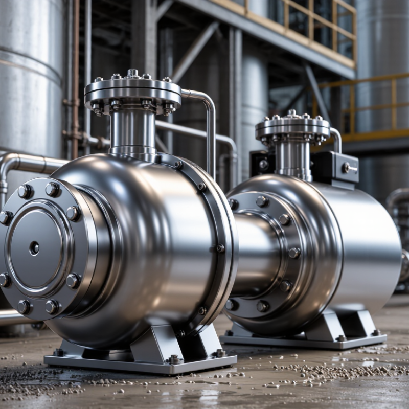
Diaphragm pumps rely on a simple positive-displacement cycle. Two flexible diaphragms move alternately inside separate chambers. Compressed air, hydraulic fluid, or mechanical drive powers this movement. In an air-operated design, an air distribution valve shifts pressure from one chamber to the other. The diaphragms then pull liquid through the inlet check valve and push it through the outlet valve. The valves prevent backflow. Small details matter.
The structure has four working elements: diaphragms, liquid chambers, check valves, and a drive section. The diaphragm separates the pumped liquid from the drive mechanism. This separation reduces shaft-seal leakage and supports handling of abrasive, viscous, or chemically aggressive fluids. The U.S. Department of Energy reports that pumping systems can represent 25–50% of electricity use in some industrial facilities. A diaphragm pump can reduce energy waste when its air pressure, stroke rate, and pipe size match the process demand, although compressed air is not automatically efficient.
In practical service, operators should inspect diaphragm fatigue, valve-seat wear, icing, and pulsation. The design looks forgiving. It is not. Excessive discharge pressure can stall the pump, while undersized suction piping may cause unstable flow. The Hydraulic Institute recommends evaluating system resistance, operating point, and maintenance conditions rather than selecting pumps by flow alone. A 2023 report from Grand View Research valued the global diaphragm pump market at more than USD 6 billion, reflecting broad industrial adoption. Market growth does not remove the need for careful sizing. Mistakes remain expensive.
| Data Dimension | Structure or Operating Detail | Industrial Value | Typical Data or Performance | Key Selection Consideration |
|---|---|---|---|---|
| Primary Pump Type | Positive-displacement pump that moves fluid by alternately expanding and contracting one or more flexible diaphragms. | Provides controlled displacement and reliable transfer of liquids, slurries, and fluids containing suspended solids. | Positive displacement | Select the pump according to required flow, discharge pressure, fluid viscosity, solids content, and chemical compatibility. |
| Main Components | Typical assemblies include the pump body, diaphragm, air or mechanical drive, inlet and outlet manifolds, check valves, valve seats, and fasteners. | A modular structure simplifies inspection, replacement of wear parts, and maintenance planning. | Two fluid chambers are common in air-operated double-diaphragm designs. | Confirm that wetted components are suitable for the process fluid and operating temperature. |
| Diaphragm Function | The diaphragm separates the drive mechanism from the pumped fluid while flexing to create suction and discharge strokes. | Reduces the risk of shaft-seal leakage and protects the drive side from direct fluid contact. | Available diaphragm materials commonly include elastomers and thermoplastics, depending on the application. | Evaluate chemical resistance, abrasion resistance, temperature limit, and expected cycle life. |
| Suction Stroke | When the diaphragm moves away from the fluid chamber, chamber volume increases and pressure decreases. The inlet check valve opens while the outlet valve closes. | Allows the pump to draw fluid into the chamber without a separate priming system in many installations. | Self-priming capability is common, but actual suction lift depends on fluid properties, piping, and pump design. | Keep the suction line short, adequately sized, and free from air leaks. |
| Discharge Stroke | When the diaphragm moves toward the fluid chamber, chamber volume decreases and pressure increases. The inlet valve closes while the outlet valve opens. | Creates a repeatable discharge cycle and supports metered or intermittent transfer. | Flow is pulsating because fluid is delivered in discrete diaphragm strokes. | Use a pulsation dampener, flexible connector, or suitable control arrangement when smooth flow is required. |
| Drive Options | Industrial diaphragm pumps may use compressed air, electric motors, solenoids, or mechanical actuators, depending on the design. | Enables selection for hazardous areas, portable service, automated dosing, or fixed process lines. | Air-operated designs regulate flow by adjusting air supply pressure or cycle frequency. | Check available utilities, control requirements, energy efficiency, and area classification. |
| Flow Control | Flow is generally controlled through stroke frequency, drive speed, air pressure, or a combination of these factors. | Supports flexible operation across different production rates. | Air-operated flow can often be adjusted while the pump is running. | Do not restrict the discharge to control an air-operated pump without verifying the manufacturer’s operating limits. |
| Pressure Capability | The pump develops discharge pressure according to the drive system, diaphragm design, valve arrangement, and process conditions. | Suitable for many transfer, feeding, filtration, coating, and chemical-handling duties. | Many air-operated industrial models are designed for discharge pressures around 7 bar, with some models rated higher. | Use the specified maximum working pressure for the selected model; never exceed the rating of the pump or piping system. |
| Flow Capacity | Capacity depends on chamber size, stroke volume, cycle rate, fluid viscosity, suction conditions, and discharge pressure. | One pump family can often cover a broad range of transfer duties. | Industrial models range from low-flow units to large pumps capable of hundreds of litres per minute; exact capacity is model-dependent. | Size the pump using the actual operating point rather than the maximum catalog flow alone. |
| Solids Handling | Large, low-shear flow passages and check valves can allow the transfer of liquids containing suspended particles. | Useful for sludge, wastewater, ceramic slip, pigments, mining fluids, and other abrasive or solids-bearing media. | Passage size and allowable particle diameter vary substantially by pump design. | Specify maximum particle size, concentration, hardness, and required abrasion resistance. |
| Shear Sensitivity | Diaphragm pumps generally operate at lower fluid velocity and lower rotational speed than many centrifugal pumps. | Can reduce damage to shear-sensitive fluids and help preserve product consistency. | Actual shear level depends on stroke rate, valve geometry, fluid viscosity, and system pressure. | Validate performance with the real fluid when handling emulsions, biological materials, or delicate suspensions. |
| Dry-Running Tolerance | Many air-operated diaphragm pumps can tolerate short periods of dry running because there is no mechanical shaft seal requiring liquid lubrication. | Improves resilience during empty-tank conditions or interrupted supply. | Dry-running capability is design-specific and may increase diaphragm or valve wear. | Confirm the permitted duration and operating conditions before relying on dry running. |
| Leakage Control | The diaphragm forms a barrier between the pumped fluid and the drive mechanism; double-diaphragm configurations can include a monitored space between diaphragms. | Helps contain hazardous, toxic, corrosive, or valuable fluids. | Leak detection options depend on the pump construction and monitoring system. | Use suitable secondary containment and a diaphragm-monitoring method for critical services. |
| Materials of Construction | Common pump-body materials include engineered plastics, aluminium, stainless steel, and other corrosion-resistant alloys. Diaphragms and valves use application-specific elastomers or thermoplastics. | Allows adaptation to corrosive chemicals, abrasive slurries, food-related fluids, and general industrial liquids. | Material compatibility is determined by concentration, temperature, pressure, and exposure time. | Review a chemical-compatibility chart and verify the complete wetted path, not only the pump body. |
| Maintenance Requirements | Routine service normally focuses on diaphragms, valve balls or discs, valve seats, air distribution parts, seals, and fasteners. | Wear parts can often be replaced without changing the complete pump installation. | Maintenance interval depends on cycle rate, abrasiveness, chemical exposure, temperature, and air quality. | Install isolation valves, provide access for service, and maintain clean, dry compressed air when required. |
| Energy Consideration | Air-operated pumps are simple and versatile but may have higher energy consumption because compressed air generation is relatively energy-intensive. | Offers operational flexibility where compressed air is already available or electrical equipment is restricted. | Energy use varies with air pressure, flow rate, back pressure, pump efficiency, and compressor performance. | Compare total operating cost, including compressed-air generation, maintenance, and process downtime. |
| Typical Industrial Uses | Common duties include chemical transfer, wastewater handling, paint and coating transfer, sludge movement, filtration-feed service, printing fluids, and abrasive slurry transfer. | One pump principle can serve many fluid-handling tasks across process industries. | Application suitability depends on fluid compatibility and the required flow-pressure operating point. | Provide complete process data before final selection: fluid, temperature, viscosity, density, solids, flow, pressure, and suction conditions. |
Note: Performance values are general industrial guidance. Actual flow, pressure, suction lift, temperature range, materials, and service life depend on the specific pump design and operating conditions.

Universal Pumping
625 Apache Trail
Woodstock, GA 30189
Mon - Fri | 9:00 AM - 5:00 PM
Universal Pumping is staffed with industry professionals with 20-45 years experience with high pressure pumping systems. We represent only the “elite producers” in pump manufacturing: Britain’s EMS and Germany’s EMMERICH. Our engineering and manufacturing approach is conservative, and we do not use “guess work” in the design or sales of our pumping and filtration equipment.


