Universal Pumping | High Pressure Pumps
High Pressure Pumps for Difficult to Pump Slurry, Sludge, and Food Waste.
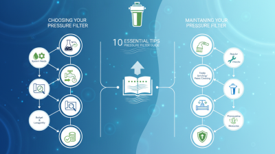
Choosing the right pressure filter begins with the process it must serve, not with a product label. The fluid, target particles, flow rate, and operating pressure all matter. A filter sized for clean water may perform poorly with a viscous liquid or changing solids load. Small details count.
Start by defining what needs to be removed. Particle size, contamination level, and the required outlet quality help determine the filtration rating and media. Then compare the expected flow with the filter’s capacity and allowable pressure drop. A narrow housing or undersized element can restrict flow and require frequent replacement. Check the full operating range, including temperature and pressure fluctuations.
Material compatibility deserves equal attention. Seals, housing, and filter media should suit the fluid and cleaning method. For example, a process using warm, mildly corrosive liquid may need different materials than a cool water line. Confirm that specifications come from reliable manufacturer documentation, and ask for test conditions when performance claims seem broad. Numbers need context.
Maintenance is part of the selection, too. Consider element availability, changeout access, cleaning requirements, and how pressure differential will be monitored. A low purchase price can be misleading if replacements are costly or downtime is frequent. In practice, the first specification rarely tells the whole story. Actual process data may be incomplete, so verify assumptions with operating records or a qualified filtration specialist before final selection. The best pressure filter is not always the most elaborate one. It is the unit that consistently meets the process needs, fits the installation, and can be maintained safely over time.
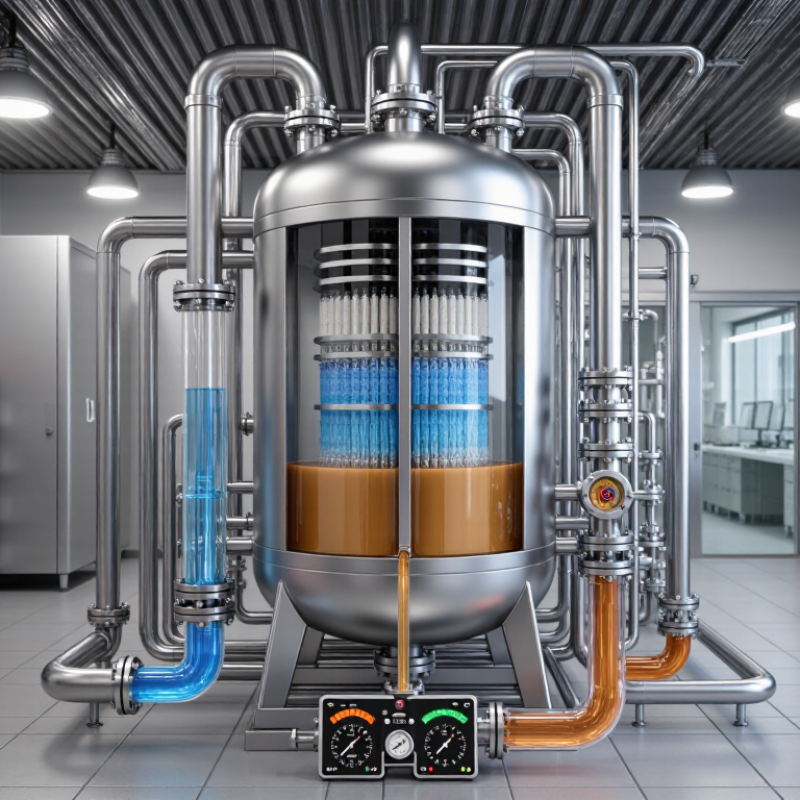
Start by describing what the filter must remove and how clean the outlet needs to be. Specify the target particle size, solids concentration, and acceptable downstream quality. “Clear water” is not a useful measurement by itself. A process with fine, sticky particles behaves differently from one containing coarse grit. Record the fluid’s viscosity and temperature, since both can change flow and filtration performance.
Then map the operating conditions across a normal shift, not just at startup. Note the required flow rate, inlet pressure, pressure fluctuations, and expected solids loading. Check whether the fluid may corrode or swell filter materials. Establish the maximum acceptable pressure drop and how often operators can service the unit. A clean-water test can mislead when real fluid is warmer or carries more solids. It is easy to overlook brief surges; those may still affect sizing.
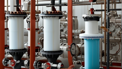
Pressure filter selection starts with the contaminant, not the vessel. Bag and cartridge filters suit suspended solids and smaller flow rates; cartridge ratings can target finer particles. Sand or multimedia units handle larger water volumes, but need backwashing as solids collect. Pressure leaf filters are often used to separate solids from process slurries. Different jobs.
Activated carbon pressure filters can reduce taste, odor, and some dissolved organic compounds, but they are not a universal chemical barrier. Membrane systems remove very fine particles and microorganisms, with performance tied to membrane integrity and fouling control. The U.S. EPA’s Membrane Filtration Guidance Manual specifies direct integrity testing at least daily for systems covered by the relevant drinking-water rule. That operating requirement matters as much as the stated pore size.
Compare the feed-water analysis, peak flow, acceptable pressure drop, cleaning method, and waste stream before choosing. A clear sample at startup can become cloudy after a production change; that detail is easy to overlook. Ask suppliers for test data using your actual fluid and particle load, not only clean-water ratings. Pressure matters. A fine filter can clog quickly when upstream solids are high, while an oversized unit adds cost without solving dissolved-contaminant problems. Cite: U.S. EPA, Membrane Filtration Guidance Manual, 2005.
Compare typical filtration ranges and applications. The ranges shown are indicative; actual performance depends on the filter media, process conditions, and particle characteristics.
How to use this chart: Choose a filter based on the required particle retention, solids load, and process needs. Bag filters are commonly used for coarse filtration, while cartridge filters suit finer polishing. Pressure leaf filters are often used for batch clarification, and sintered metal filters are useful where durable, cleanable media is required.
A pressure filter is only as effective as its media’s fit for the fluid and contaminant. Check chemical compatibility, operating temperature, and whether the target particles are fibers, grit, or fine solids. ISO 16889:2022 describes multipass testing for hydraulic filter elements. Its beta ratio offers a useful data point: a beta value of 200 means 199 of every 200 counted particles at the stated size are retained, or 99.5%. That figure is not a promise for every fluid or installation. Test conditions matter.
Pressure rating and flow capacity need equal scrutiny. Select a filter rated above the system’s maximum working pressure, including foreseeable pressure surges; a normal gauge reading is not the whole story. Then check the pressure-drop-versus-flow curve, not just a headline flow figure. ISO 3968:2017 outlines how this relationship is evaluated. For example, a unit tested at 50 liters per minute may behave differently with colder, more viscous fluid or a loaded element. Ask for data at your actual fluid viscosity and temperature. Small oversight, big pressure drop. And be honest: field conditions rarely match a clean laboratory test exactly.
How to Choose the Right Pressure Filter?
Determine the Appropriate Filter Size and Configuration
Size the filter for real operating conditions, not the pump’s nameplate alone. Record normal and peak flow, fluid temperature, viscosity, and expected solids. Flow is not everything. Viscous liquids and heavy solids loading can increase pressure drop and shorten service intervals. Compare your required flow with performance data for the actual fluid conditions. Check the allowable differential pressure and housing pressure rating, too. Pipe connection size alone is a poor basis for selection.
Match the configuration to the process and maintenance routine. A single housing may suit steady operation; a duplex setup can allow element changes without stopping flow. Check inlet and outlet orientation, drain access, headroom, and clearance for removing elements. For fine filtration, confirm the target particle size and whether the rating is nominal or absolute. Verify that wetted materials and seals are compatible with the fluid and cleaning method. A compact unit may fit the pipework but leave too little room for service. Easy to overlook.
Tips: Record a clean pressure-drop reading after startup as a baseline. Track flow and differential pressure together; either value alone can mislead. Allow a modest capacity margin for normal variation, but avoid oversizing blindly. Actual conditions can be messier than the design sheet.
Use this guide to match a pressure-filter configuration to the liquid, required flow, particle-removal target, and operating conditions. Final sizing should be confirmed using process data and, where needed, filter-media testing.
| Selection Dimension | What to Determine | Practical Guidance | Sizing or Configuration Check |
|---|---|---|---|
| Process Requirements | |||
| Liquid and operating conditions | Liquid composition, temperature, viscosity, chemical compatibility, and whether the fluid is clean, particle-laden, or slurried. | Check that the vessel, seals, baskets, and filter media are compatible with the fluid and its operating temperature. | Use the maximum operating temperature and pressure, not only normal conditions, when specifying the equipment. |
| Required flow rate | Normal, minimum, and peak flow; continuous or batch operation; and any planned future capacity increase. | Size for the required peak duty while considering acceptable pressure drop and the available operating pressure. | For parallel units, divide the total flow by the number of units expected to operate simultaneously. |
| Particle-removal target | Required downstream cleanliness or the particle size that must be retained. | Specify the required rating and whether it is nominal or absolute. These terms are not interchangeable; confirm the test method and retention performance with the media supplier. | Base the rating on the process requirement, not solely on the smallest particle observed in a sample. |
| Solids loading | Suspended-solids concentration, particle characteristics, and expected solids collected between cleaning or media changes. | High or variable solids loading may require greater dirt-holding capacity, a larger filtration area, more frequent cleaning, or a backwashable design. | Use representative samples or operating history to estimate service life and cleaning frequency. |
| Pressure drop | Available inlet pressure, allowable differential pressure, and the pressure drop at which cleaning or element replacement is required. | Monitor differential pressure across the filter. A rising differential pressure commonly indicates increasing solids accumulation or element blockage. | Confirm the vessel pressure rating and differential-pressure limits for the vessel, media, and internals. |
| Configuration Comparison | |||
| Single-bag housing | Moderate flow with routine change-out of disposable bag media. | Provides a simple arrangement for coarse-to-fine particle capture, depending on the selected bag and process. | Check the bag dimensions, support basket, seal arrangement, and change-out access. Capacity depends on media and fluid conditions. |
| Multi-bag housing | Higher flow or a need for more filter-media capacity in one housing. | Multiple bags operate in parallel within the vessel; suitable when the process and selected media allow parallel flow. | Confirm the number of bags, flow distribution, allowable differential pressure, and space for safe bag replacement. |
| Cartridge housing | Applications needing defined cartridge ratings, finer particle capture, or replaceable elements. | Available in different cartridge lengths, media types, and retention ratings. Cartridge performance is media- and test-dependent. | Determine cartridge count from the supplier’s recommended flow per element for the actual fluid, temperature, and solids load. |
| Duplex or changeover arrangement | Processes that need filtration to continue while one side is isolated for cleaning or media replacement. | Two filter chambers can be arranged so one is in service while the other is isolated, subject to the valve and piping design. | Check whether either chamber must handle the full process flow and whether the changeover procedure maintains required filtration. |
| Backwashable pressure filter | Suitable applications where collected solids can be removed by backwashing and the process can accommodate a backwash cycle. | Can reduce routine media replacement, but performance depends on solids characteristics, backwash conditions, and the filter design. | Verify backwash flow, pressure, duration, waste handling, and the impact of each cycle on process availability. |
| Pressure filter press | Slurry dewatering where the objective is to separate solids into a cake and recover filtrate. | Selection depends on slurry properties, required cake dryness, cycle time, and cloth compatibility. | Estimate chamber volume and filtration area from representative slurry testing; liquid-flow sizing alone is not sufficient. |
| Sizing Method and Specification | |||
| Filtration area | Flow rate and the design flux appropriate for the fluid and filter media. | For area-based sizing, use: required area = design flow rate ÷ validated design flux. | Design flux is application-specific. Obtain it from supplier guidance, pilot testing, or comparable operating data; do not treat a generic flux as universal. |
| Illustrative area calculation | Example only: a process flow of 10 m³/h and an assumed, validated design flux of 1 m³/(m²·h). | Required area = 10 m³/h ÷ 1 m³/(m²·h) = 10 m². | This example demonstrates the calculation only. The assumed flux is not a general recommendation and must be validated for the specific application. |
| Continuous availability | Required operating hours, cleaning or replacement duration, and acceptable process interruption. | Consider a duplex arrangement, parallel housings, or installed spare capacity when filtration must continue during service work. | Define whether the stated design flow is required with one unit out of service. |
| Final purchase specification | Flow, fluid properties, operating and design pressure, temperature, particle-removal target, solids loading, and connection details. | Include the required materials of construction, instrumentation, drain and vent connections, and maintenance access. | Request confirmation of capacity, clean and terminal differential pressure, media compatibility, and applicable pressure-vessel requirements. |
Important: Filter capacity and service life vary with fluid viscosity, particle size and shape, solids concentration, media construction, and operating conditions. Confirm final filter selection with application-specific data and the equipment supplier.
A pressure filter’s purchase price tells only part of its story. Check the expected service interval, element availability, cleaning method, and time needed for changeouts. Ask operators to estimate hours spent isolating, draining, opening, and restarting the vessel. Small delays repeat. The U.S. Department of Energy’s Operations & Maintenance Best Practices Guide reports potential predictive-maintenance savings of 8–12% over preventive maintenance and 30–40% over reactive maintenance. Those figures are not guarantees, but they show why maintenance planning matters.
Safety deserves equal attention. Match the vessel’s pressure and temperature ratings to actual operating conditions, including start-up surges. Confirm that pressure relief devices, gauges, and differential-pressure indicators suit the installation. A rising differential pressure can signal a loaded element; ignoring it may increase downtime or stress equipment. Check whether the filter can be isolated and depressurized before servicing. No shortcut here.
Compare lifecycle costs over the same operating period. Include replacement elements, energy for pumping, labor, disposal, inspections, and production losses during maintenance. A lower-priced unit can cost more if elements clog quickly or require frequent manual cleaning. The DOE’s Federal Energy Management Program recommends lifecycle-cost analysis for comparing long-term ownership costs. Ask suppliers for documented flow and pressure-drop data, then verify assumptions against your own fluid and operating profile. Real plants are messy; estimates need review.
Universal Pumping
625 Apache Trail
Woodstock, GA 30189
Mon - Fri | 9:00 AM - 5:00 PM
Universal Pumping is staffed with industry professionals with 20-45 years experience with high pressure pumping systems. We represent only the “elite producers” in pump manufacturing: Britain’s EMS and Germany’s EMMERICH. Our engineering and manufacturing approach is conservative, and we do not use “guess work” in the design or sales of our pumping and filtration equipment.